PRODUCT
고객님께 적합하고 효율적인 최선의 솔루션을 제안하겠습니다.
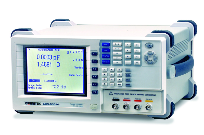
gwinstek>>Gwinstek>> LCR-8000G 시리즈
|
주요 특징 |
||
|
 1MHz/5MHz/10MHz 테스트 주파수
|
Friendly Intuitive User Interface |
|
The LCR-8000G Series is designed to perform precision impedance measurements over a wide frequency range of 20Hz~1MHz for LCR-8101G, 20Hz~5MHz for LCR-8105G and 20Hz~10MHz for LCR-8110G.The instrument is capable of measuring 11 different parameters with0.1% basic accuracy, which meets the precision measurement requirements of components and modules used in the RF circuits. The large LCD display with single-layer operation menu of LCR-8000GSeries provides users with ultimate convenience to plug and play without much learning time.
|
|
Pass/Fail Function with Judgment Alarm |
|
In the Pass/Fail test, primary parameter measurement result is compared with user-defined limits and the pass or fail result is then displayed. Three methods, including absolute limit, percentage and delta limit, are available for Hi(high) and Lo(low) limit setting based on the nominal test value. The Pass/Fail test checks whether the parameter measurement result sits within the limits, then display "PASS" for within the limits, or "LO" for lower than the low limit, or "HI" for higher than the high limit. A scale and bar for displaying measurement result is shown at the center of the screen to give a graphical identification, which greatly reduces operator's load in a long time inspection work. This scale and bar also facilitate the adjustment of the variable components. Either Pass or Fail result can be set with a buzzer alarm, which makes component or material sorting easy with sound identification.
|
|
Multi Step Mode |
|
The Multi-Step mode is capable of running a series of measurements of a component at a number of user-defined steps in sequence automatically. Total 64 programs can be saved into the non-volatile memory, and each program contains up to 30 test steps. The parameter and Hi/Lo limits can be set respectively for each test step. After a program being properly edited, the instrument can run through all the measurement steps either at a press of the button under the Manual Trigger selection, or automatically run the program by detecting the connection of a DUT under the Auto Trigger selection. When all the test steps are completed, the screen shows the measurement reading of the parameter being selected for each step with Pass, HI, or LO measurement result.
|
|
Graph Mode |
|
The graph function shows the component characteristics in visual manner. Either voltage sweep or frequency sweep can be selected for horizontal scale. Just select the parameter, and set the start/stop voltage or the start/stop frequency of the sweep, LCR-8000G will run through the sequence of measurements and show the results on a graph. This graphical parameter measurement performs the characteristic verification of components and materials over the response to the changes in AC test frequency or AC test voltage without the need of complex programming of an external controller. When the graph gets out of the vertical range, the LCR-8000G Series can automatically adjust the scale to get full test information. On the graph the marker operation is available for detailed observation...
|


|
LCR-8000G Series |
|
|
TEST FREQUENCY |
|
|
20Hz ~ 10 / 5 / 1 MHz, 5 Digits, ±0.005% |
|
|
INPUT IMPEDANCE |
|
|
100Ω |
|
|
BASIC ACCURACY |
|
|
±0.1% (R, Z, X, G, Y, B, L, C) |
|
|
TEST SPEED |
|
|
AC (> 2kHz) |
DC |
|
TEST SIGNAL LEVELS |
|
|
≦3MHz:10mV~2Vrms, 1mV/Step or 10mV/Step, 2%±5mV |
|
|
SHORT CIRCUIT CURRENT |
|
|
Max. 20mA |
|
|
MEASUREMENT RANGES |
|
|
R, Z, X |
0.1mΩ ~ 100MΩ |
|
G, Y, B |
10nS ~ 1000S |
|
L |
0.1nH ~ 100kH |
|
C |
0.01pF ~ 1F |
|
D |
0.00001 ~ 9.9999 |
|
Q |
0.1 ~ 9999.9 |
|
θ |
-180° ~ +180° |
|
Rdc |
0.1mΩ ~ 100MΩ |
|
MEASUREMENT PARAMETERS |
|
|
Impedance (Z), Phase Angle (θ), Inductance (L), Capacitance (C), AC Resistance (Rac), Quality Factor (Q), Dissipation Factor (D), Admittance (Y), Conductance (G), Reactance (X), Susceptance (B), DC Resistance (Rdc) |
|
|
SERIES OR PARALLEL EQUIVALENT CIRCUIT |
|
|
C + R, C + D, C + Q, L + R, L + Q, L + D |
|
|
SERIES EQUIVALENT CIRCUIT ONLY |
|
|
X + R, X + D, X + Q |
|
|
PARALLEL EQUIVALENT CIRCUIT ONLY |
|
|
C + G, B + G, B + D, B + Q, B + R, L + G |
|
|
POLAR FORM |
|
|
Z + Phase Angle, Y + Phase Angle |
|
|
LCD DISPLAY |
|
|
320 x 240 DOT-MATRIX |
|
|
INTERFACE |
|
|
RS-232, GPIB |
|
|
POWER SOURCE |
|
|
AC 115V(+10% / -25%), 230V(+15% / -14%) (Selectable), 50/60Hz |
|
|
DIMENSIONS & WEIGHT |
|
|
330(W) x 170(H) x 340(D)mm, Approx. 5kg |
|